The first few days of the week we're dedicated to write down the first version of my thesis indice, where I defined all the topics that I'll be writing in the next couple of weeks. This process allowed me to review some of the work I've done since the begining of this project and how far I've come.
Apart from the usual chapters of any thesis, the Introduction, the Experimental Interface, etc the core of the thesis is divided in three main chapters: the Tests and Results, the Collision Zone Detection and Ego-Motion Study. The Collision Zone Detection was my first goal when I took this challenge and I can probably say it was accomplished , although since it depends on other programs this work can only be as right as it's dependencies. After completing the first goal I started studying the efects of the Atlascar ego-motion, specially while it is turning, on the velocity given by the GNN. The work is still in development but I believe that I'm close to reaching a conclusion. The Test and Results chapter is where things got complicated for me. I find it quite hard to develop a test to prove my work. Since it is related to collisions, I have to come up with a test that proves that there will be a collision while at the same time ensuring the safety of the Atlascar and all it's components. More though must be made on this subject as it is probably the most important chapter of my thesis.
In the off time of the thesis writing I continued the last week's work. With most of the theory of the problem already defined I went on to determine the relationship between the Atlascar steering wheel and the wheel's angle. This angle will then be used to calculate the turning center point as described last week.
Many approaches could be made to find out the angle, however due to the lack of information about the car specifications I decided to use the simple approximation as follows. Knowing the maximum wheel angle of both the inner and outer wheel (45º and 38º respectively), and the maximum steering wheel angle to both sides (635º), I first calculated the steering wheel ratio for both the inner and outer wheel with (1). With this formula I know the angle of the inner and outer wheel when the steering wheel is at a certain angle.
$$Steering~wheel~ratio = {Steering~wheel~angle \over wheel~angle}~~~~~~~~(1)$$
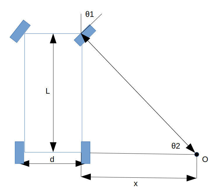
A visual description of the following terms is displayed in figure 1. After finding out the steering ratio I can now calculate the turning center point (O) with the outer or the inner wheel angle, in this case I used the inner wheel angle. With trignometric rules we can say that $\theta$1 and $\theta$2 are equal so, we can use (2) with the known wheelbase (L), and wheel angle ($\theta$1=$\theta$2) to determine $x$.
$$tan(\theta) = {L\over x}~~~~~~~~(2)$$
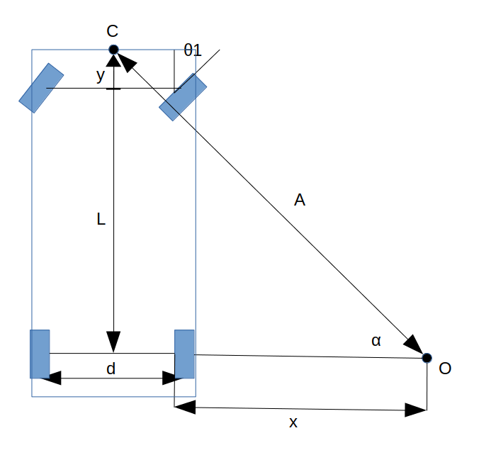
We will now use this distance $x$ to determine the distance between O and C, as displayed in figure 2. Using (3) we first determine the angle $\alpha$ and then with (4) we determine the distance $A$. The point C is an approximate point to the base_link frame, situated in the front bumper of the car and takes into account the wheelbase (L) and the vehicle front overhang (y). Since all the measurement of the VO node are made in reference to the base_link frame I decided to also determine the distance between this point to the turning center point rather than use the points of the wheels.
$$tan(\alpha) = {L+y\over {d\over2}+x}~~~~~~~~(3)$$
$$sin(\alpha) = {L+y\over A}~~~~~~~~(4)$$
We now have the turning circle defined, however it is important to notice that this was an approximation as while using the information of the Atlascar manual these dimmensions won't be the same (Atlascar manual claims the minimum turning radius is 4.5 meters, and using these calculations we get about 4 meters). This difference can be due to the fact that the car might not use the very same Ackermann geometry rather than an derivation of it.
After all the calculations were done I started working on representing on Rvizz the approximate path that the Atlascar will take in the next scan. This was made by subscribing to Diogo's node which publishes the car's velocity and steering wheel angle, in the NominalData topic. The steering wheel angle was used to determine the turning circle as seen before, wich in fact will be the path the car will take. The lenght of this path was determined using the car angular velocity ($\omega = {v\over r}$) wich is the same as saying that the car will cover $\omega$ radians per scan. With this information we can set the circle to start at the initial $\alpha$ angle and finish at $(\alpha + \omega)*size~factor$. This size factor is currently at 20 and was added due to the low values of $\omega$. The results of this can be seen in the video below with the path in blue and a line between the rear axle of the car and turning center point in red.