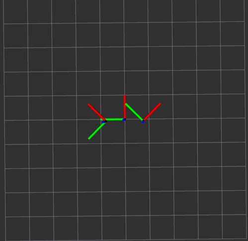
After the first representation of the velocity cone last week I started working on the information that the VO node will publish. To better understand the work that has been done this week we need to first understand the raw data that the lasers gives. This laser data is subscribed, as already explained in the past weeks, by the simple_planar_pc_generator node. This node is responsable for filtering the data, transform it to a point cloud, and then assign a frame to the points in the point cloud. A frame is a coordinate system with x, y, and z axis and the atlascar as one per sensor/camera. All these coordinate systems have a relationship between each other, like a family tree we have a parent and a child frame. The parent links to a child frame by a translation and/or rotation. The parent frame in the atlascar is the "base_link", and it is the coordinate system that I will be using as reference, as it's located at the front of the veihicle. Since the lasers are located at the left and right of my reference frame, as seen on image 1, and the point cloud data is related to one of these (depending on the frame selected in the simple_planar_pc_generator), to do the calculations needed in the VO node, I have to translate and rotate the points I will use latter on. To do this I need to know the relationship between the laser frame and "base_link", and then do the math. At first I did this calculation by "hand", multiplying the transformation matrix between the two frames by the points, but in the end I found out that the tf library has a function wich does this, making my job easier (even though it was already done). I now have all the information given by the GNN (centroid, initialpose, finalpose, velocity) related to my frame.
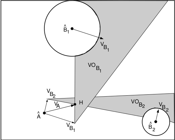
Since I'll be having multiple obstacles on the road, and by following the literature on the velocity obstacles subject as in Fiorini and Shiller 1998, in this paper it is stated that "To consider multiple obstacles, it is useful to establish an equivalent condition on the absolute velocities of A", being A the Atlascar. This means that instead of using the relative velocity between the Atlascar and every single obstacle, it is more useful to simply translate the velocity cone of each atlascar/obstacle pair by the velocity vector of the obstacle. I can then use the absolute velocity of the atlascar to determine if there will be a collision, that is if the VA is within one of the VO's in Fig 2.
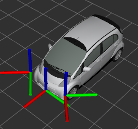
In order to get a better sence of how far objects are around the atlascar, I started working on displaying a meshed representation of the car itself as I have seen in some of Professor's Miguel demonstrations in the ROS course. I started reviewing some of his work posted on the lardemua repository on github, in search of a URDF file. URDF is a xml format file for representing a robot on Rviz, however in Professor's Miguel work he uses xacro files, a xml macro language, wich is a shorter and more readable xml file using macros that expand to larger xml expressions. This xacro file has all the links (frames) used by the Atlascar with the relationships between each other, and a macro for a URDF mesh of the car itself. Despite many research I conclude that the time needed to be invested in trying to understand xacro files wasn't worth it and since I only need this for a visual representation I just used the URDF mesh and implemented it on my visualization launch file.
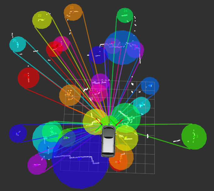
As seen in the past weeks, the GNN node represents the targets on Rviz with different colors, so as to better identify wich cone and circle belongs to witch target I added the color information of the targets marker to the cone and circle marker. This was done by subscribing to the targets marker, and collecting all the colors and ID's of the multiple targets, and then associate to the ID's of the cones and circles, since they have the same ID as of the target they correspond to.
After weeks of work with the same data I decided it was time to go and record a new bagfile, especially one with car moving. So following the tutorial on the Atlascar2 repository on lardemua github page, made by Professor Miguel, I did some bagfiles with the help of my colleague Diogo. One on his garage, one driving to DEM and another driving back. However even after checking if the bagfile was properly done in the atlas machine, when I got home I couldn't get it to play the recordings, giving me an "UnicodeDecodeError". I've searched around the internet but didn't get any solution to my problem, only found out it is related to UTF-8 to ASCII conversions. I found it really strange that it worked in the atlas machine but not im my personal computer and I wounder if there were any troubles while transfering the files via a USB drive. I already asked for professor's Miguel aid on this issue, but in the meanwhile I'm scheduling another trip to Aveiro, this time to run my node live in the Atlascar.
As of the time of writing, I'm working on computing the time to collision with the obstacles, wich was an objective proposed by professor Vitor for this week. This problem doens't seem too complicated, however before I can calculate this, I first need to determine if the Atlascar is indeed in course of collision with the obstacle, wich I'm only now working on.